Table of Contents
The intent of this section is to clarify and add to what is shown in the official plans. In case of conflict between these specifications and the official plans, these specifications shall govern. It is impossible to foresee every conceivable innovation which may be thought of in the future or mention every suggestion that has been ruled illegal in the past. When in doubt, it must be assumed that anything in connection with the boat, sails and rigging which is not clearly covered by the official plans and specifications or “Measurer’s Rulings” is illegal and that a ruling must be obtained from the Chief Measurer before attempting such an innovation. All such decisions shall be made with the best interests of the class in mind, rather than any technical misconstruction of drawing or text.
The Association reserves the right to declare ineligible any boat which does not conform to the spirit as well as the letter of all rules and specifications.
1. General
- The hull and spars must be constructed by a manufacturer licensed by the HCIA and shall comply with all of the certified measurements indicated in these specifications.
- The boat number shall be cut into the keelson aft of the centerboard trunk in digits at least two inches high.
- Minimum all up weight of the Highlander shall be 830 pounds. All up boat includes only hull, flotation, centerboard, rudder, tiller, mast, boom, main sheet, fixed hardware and standing rigging. Boats which weigh less than the minimum must be brought up to minimum by permanently attaching one-half of the increase forward of Station 6 and one- half of the increase aft of Station 14. Any other method of adding boat weight must be submitted to the Chief Measurer for approval in advance.
- The hull of a Highlander may be constructed of composite materials and/or wood and shall include sufficient flotation to support boat and crew when capsized.
- Hull or Transom Bailers may be Used (Recommend Contacting the Builder Before Installing for Guidance and Instruction).
- The type of Bow Fitting is Optional.
- The Half-Round Bow Molding used on Some Wooden Boats may be Removed.
- The Use of Any Device Which Spans the Cockpit Opening (used to mount jib blocks, mid- boom travelers, etc.) is prohibited.
- The Use of Any Type of Electronic or Mechanical Speed Indicators During a Sanctioned Regatta is Prohibited.
- The Use of Any Electronic Equipment that Displays or Provides any Information Other Than Time, Compass Heading or Change in Compass Heading is Prohibited While Racing. Currently the Tack-Tick (Model T060) and Velocitek Shift and Nautalytics Alloy Compass are the Only Electronic Compasses Which are Class Legal.
- The Use of VHF Radios or Cell Phones is Allowed During Racing Provided Their use is for Emergency Purposes Only. The Sailing Instructions for a Specific Event may Permit the Use of VHF Radios for Race Management Purposes but Their use Shall be Limited to That Specified in the Sailing Instructions. Under No Circumstances Shall any Electronic Device be Used to Receive, Display or Transmit any Information That Would Constitute Outside Help, Even if that Help is Available to All Competitors.
- The Use of Hull Coatings Which Leach Chemical Agents into the Boundary Layer to Decrease Drag are Prohibited.
- The Use of Hull Texturing Such as Riblets or Anything Designed to Aerate, Channel or Otherwise Trip the Flow Within the Boundary Layer is Prohibited.
- The Use of Wax or Polymer Hull Coatings Containing Teflon is Permitted.
- Hiking Straps are Permitted But They Must at All Times be Below Deck Level Measured at the Cockpit Opening When Determined or Sighted Athwartship (see Figure 2).
2. Spars
- Mast shall be as shown in official drawings. New mast extrusions must be purchased from the official Highlander Class licensed builder and once fully rigged shall meet the dimensions shown in the official mast drawing. Any modifications to the mast cross-section or additional rigging not shown in the official drawing must be approved by the Chief Measurer.
- Maximum diameter of Main, Jib and Spinnaker halyard sheaves shall be 1” unless the height of the centerline of the sheave axel is less than the maximums allowed in Figure 4. The sheave diameter can increase by 2 times the amount the sheave axel is below the maximum. For example, if the sheave axel centerline is 1/2” below the maximum allowed in Figure 4, then the sheave diameter can be up to 2” or if the sheave axel centerline is 1” below maximum then the sheave diameter can be up to 3”.
- Maximum mast step thickness is 3/4”. If an aluminum mast is used an additional butt plate, not to exceed 1/4 inch thickness may be used.
- A Mast Cap is Required on Aluminum Masts and May Be Made of Wood, Aluminum, Plastic or Hard Foam.
- Boom must be purchased from the official Highlander Class builder and shall meet the official drawing.
- The minimum height of the gooseneck above the butt of the mast shall be waived on all CustomFlex built masts whose gooseneck is as installed by that builder.
- The maximum length of the spinnaker pole, including fittings, shall be 84 inches. Only one spinnaker pole may be used at any time during a race however extra spinnaker poles may be carried on board. Pole may be used as whisker pole on jib when spinnaker is not set.
- USYRU RULE 64.3 MODIFYING “CLOSE PROXIMITY” – It is permissible to allow spinnaker guy to run freely through the pole end fitting.
3. Standing and Running Rigging
- No locking device aloft for halyards is permitted. Halyards must be secured in the bottom three feet of the mast or within the hull. Weight of sails must be carried on halyards while sails are set.
- A separate spinnaker halyard shall be used, located either inside or external to the mast. It shall be located as shown in Figure 4. The center of attachment of an external halyard must not exceed the maximum dimension and also must lie within the angle formed by the leading edge of the mast and a line that intersects the point of maximum allowable height and the bow at Station 0, excluding hardware.
- The standing rigging shall conform to the official drawing without variation and shall not be adjusted in any way while racing. No change in the places of entry of the side shrouds into the deck (as called for in the official plans) shall be made.
- A full width mainsheet traveler is permitted, provided it does not extend athwartship beyond the outside of the hull. All travelers must be located within two inches of the after face of the transom.
- An adjustable mast step is legal, providing it is fixed so it cannot be adjusted during a race.
- Adjustable turnbuckles on the shrouds are not permitted.
- The mast spreaders may be shortened. However, the distance from the end of the spreader, excluding the adjusting fitting, to the side of the mast cannot be less than 9 inches. Spreaders must be constructed of 3/8 inch O.D. hollow stainless steel tubing.
- Any mechanism which facilitates adjustment of standing rigging during a race must be bolted in place or otherwise rendered inoperative for racing in such a way that independent verification is possible. The forestay/halyard/T-bar jib rigging as originally designed is permitted.
4. Centerboard and Trunk
- Centerboard material is optional.
- Cocking or jibing centerboards are disallowed.
- Maximum weight 88 pounds, minimum weight 60 pounds.
- Side profile shall conform to the official plans.
- Method of hoist is optional.
- Maximum thickness of the portion of the centerboard that is unhoused when in the full- down position shall be 15/16 inch and the minimum thickness shall be 3/4 inch.
- The trailing edge shall either be rounded or squared-off flat. If rounded, the edge shall not be less than 1/8 inch in diameter. If squared-off, the flat edge shall not be less than 1/8 inch wide. Sharper trailing edges are prohibited.
- Rollers shall be a minimum of 2 inches in diameter.
- The centerboard trunk and slot shall be as designed. Centerboard shall be unrestricted in its travel on the trunk, i.e., no notches permitted in the centerboard trunk so as to lower the board in the water.
5. Rudder and Tiller
- Rudder material is optional.
- Maximum thickness of blade portion extending below the bottom of the transom shall be 15/16 inch.
- Kick-up rudders must be pinned in a full-down position in all National or sanctioned regattas.
- Design of the tiller is optional. Hiking sticks are permitted.
6. Sails: Measuring Sails:
- Sails shall be measured only when absolutely dry.
- All measurements shall be taken to outside of cloth, boltrope and headboard.
- All measurements shall be made with no tension is applied to the sail, but the cloth shall be smoothed out except that the luff and foot of the main and jib and the sides and foot of the spinnaker shall be measured under a five (5) pound tension.
- Mid-luff dimension of main and jib is found by folding the head down to the tack and marking the mid-point. The mid-leech likewise, is found by folding the head down to the clew and marking the mid-point. The sail is opened flat and measured to the edges of the sail at the marks.
- The measurement of the spinnaker mid-seam, mid-girth and upper-girth shall be taken when all interior seams are straight and parallel to each other. All three measurements of triangle required to measure each of the two girths shall be taken simultaneously and without regard for position of rest of sail. All measurements shall be taken without intervening opportunity for the stretching or shrinking of any dimension. All measurements shall be made after sail is folded along the vertical middle seam and with the luffs conforming to each other.
7. Mainsail
- Mainsails shall be made from any woven fabric not less than 3.5 oz. per running yard, 28 1/2 inches wide.
- Distance between seams is optional.
- There are no minimum measurements. Maximum measurements are shown in Figure 4.
- Up to four battens as shown in Figure 4 are permitted.
- The use of a full-length upper batten on mainsails a minimum of three years old is permitted. The location and angle of the full-length batten shall be the same as that of the original batten. The full-length top batten pocket may be installed on the opposite side of the original pocket, but only one batten may be used at any given time. The full-length batten shall be installed in a manner that will not change the curvature of the sail, as manufactured.
- Windows can be a material that is either completely clear, or may contain reinforcement fiber of any material. Reinforcing fiber must be less than or equal to 0.05 inches in diameter and can be any series of straight lines either crossing each other or non-crossing. Fiber lines may only run in one, two, or three different directions. The fibers shall have a distance between parallel fibers no less than 1.5 inches. A maximum of 21 ft2 (total) window area is permitted with a maximum of any single window being 6.5 ft2 . Windows must be located within the boundary defined by a parallel line that is 24 inches from the free edge of the mast bolt rope and a parallel line that is 40 inches from the free edge of the boom bolt rope (Figure7).
- Holes for the purpose of reefing may be installed along the luff no higher than 3 feet 6 inches above the boltrope and along the leech no higher than 3 feet 9 inches. The leech hole measurement may vary from the luff hole measurement by no more than +/- 3 inches.
- A hole in the mainsail for the purpose of controlling luff tension only is allowed with the following restrictions: only one hole, maximum diameter 3/4 inch located not more than 8 inches above the foot bolt rope and not more than 4 inches aft of the luff bolt rope.
8. Jib
- Jibs shall be made from any woven fabric not less than 3.5 oz. per running yard, 28 1/2 inches wide.
- Distance between seams is optional.
- There are no minimum measurements. Maximum measurements are as shown in Figure 5.
- Windows can be a material that is either completely clear or may contain reinforcement fiber of any material. Reinforcing fiber must be less than or equal to 0.05� diameter and can be any series of straight lines either crossing each other or non-crossing. Fiber lines may only run in one, two, or three different directions. The fibers shall have a distance between parallel fibers no less than 1.5 inches. A maximum of 5 ft2 (total) window area is permitted with a maximum dimension of a single window being not more than 40 inches in any direction. Windows cannot extend higher than a line drawn between a point that is 4 feet up from the center of the luff grommet (measured along the luff) and 4 feet up from the center of the clew grommet (measured along the leech – Figure 7).
- Up to two battens as shown in Figure 5 are permitted.
- A clewboard of any material is permitted in the jib, which shall be located as shown in Figure 5.
- A minimum number of five (5) snaps or hanks equally spaced along 80 percent of the luff must attach the jib to the forestay.
- Zippers in the luff for the purpose of changing sail shape are not permitted.
- Jibs which passed around the forestay and attach back of themselves, either by sewing or with a zipper or similar method are not permitted.
- It is not necessary for the entire jib to fall within the official sail plan triangle. However, it must meet all Class specification measurements. The head to mid-foot measurement does not include the skirt. This is unclear in the official drawing.
- Jib wire shall have a minimum diameter of 3/32â€� and may be 1×19, 7×7, or 7×19 stainless steel wire. The wire shall be SECURELY attached to the head of the sail and must be functional.
9. Spinnaker
- Spinnakers shall be woven material with no restriction on material weight.
- Distance between seams is optional.
- Dimensions and tolerances are as shown in Figure 6.
- Holes in the deck through which the spinnaker is raised and lowered are not permitted.
10. Certified Hull and Rigging Measurements
- Hull Measurements:
- L – Length Overall
- F – Forward End Of Cockpit Opening From Station 0
- R – Aft End of Cockpit Opening From Station 0
- B – Beam at Station 10, Taken to Outside of the Hull at the Sheerline
- Deck Widths, Taken from Outside of Hull to Inboard Deck Edge at: Forward End of Cockpit Opening Aft End of Cockpit Opening
- T – Height of Transom at Centerline Excluding Deck Trim
- X – Beam of Transom at Sheerline
- W – Thickness of Rubbing Strip Taken From Deck
- Hiking Straps Should be Confirmed to Meet the Below Deck Requirement
- Rudder Measurements:
- H – Vertical Length of Rudder Blade From Tip to Bottom of Cheeks (including any chamfers) Measured With Transom Edge of Rudder Cheeks Perpendicular to the Line Intersecting the Tip of the Blade
- P – Maximum Width of Rudder Blade Measured Perpendicular to Transom Edge of Rudder Cheeks
- Centerboard Measurements
- A – Length of Leading Edge of Centerboard
- Y – Width of Centerboard at One-Half A
- Centerboard Weight
- Mast Measurements:
- Height of Main Halyard Sheave Axel Centerline Above Butt of Mast
- Height of Spinnaker Halyard Sheave Axel Centerline Above Butt of Mast
- Height of Jib Halyard Sheave Axel Centerline Above Butt of Mast
- G – Height of Gooseneck Centerline Above Butt of Mast
- Boom Measurements
- BW – Width of Boom
- Overall Length of Boom From Bottom of Mast Luff Groove Including Fittings
- Foretriangle
- M – Station 0 to Forestay at Deck
- J – Foretriangle
- A Jib-Tack Fitting In-Line With The Forestay is Permitted. Position of The Forestay Must Comply With Measurements J and M.
Figure 1. Certified Hull Measurements

Figure 2. Certified Hull Measurements

Figure 3. Rudder and Centerboard Certified Measurements

Figure 4. Mast Boom and Mainsail Measurements
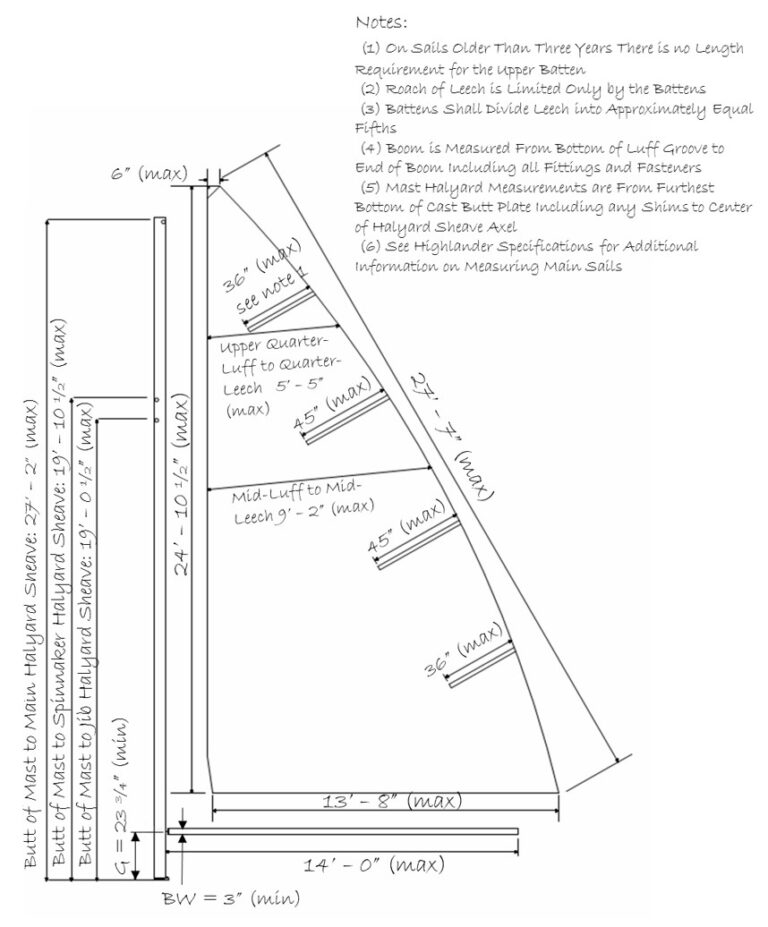
Figure 5. Jib Measurements
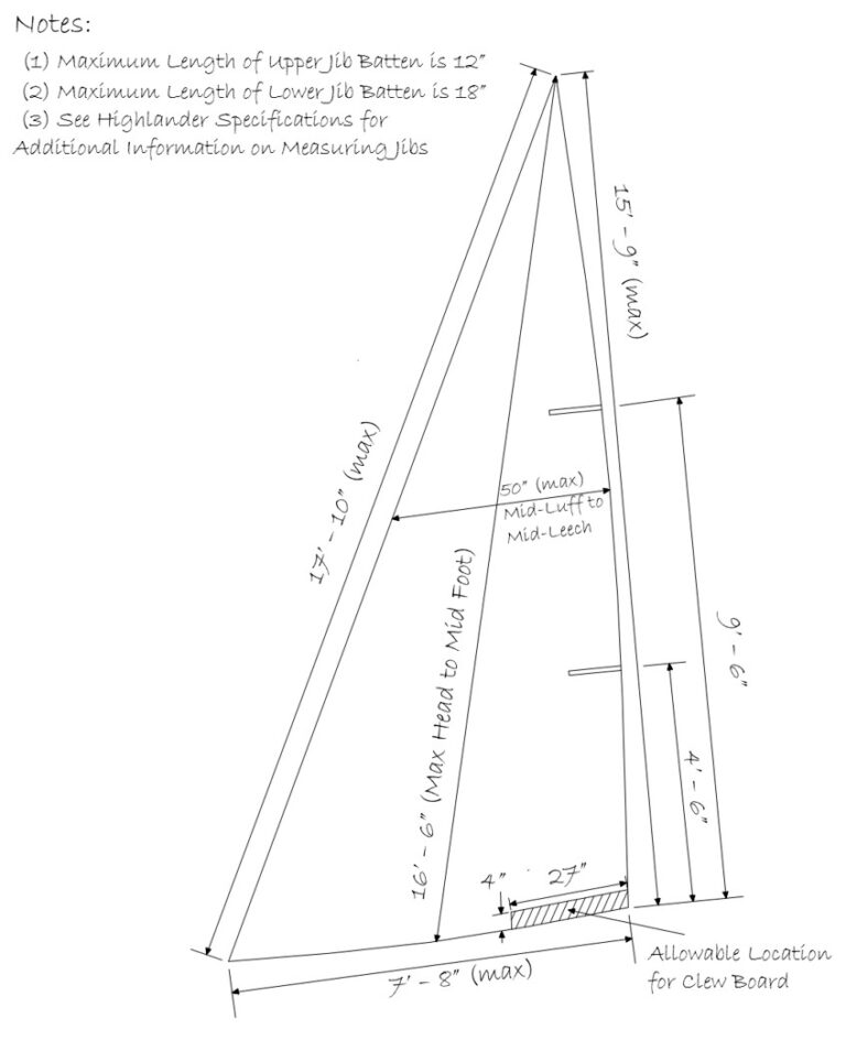
Figure 6. Spinnaker Measurements
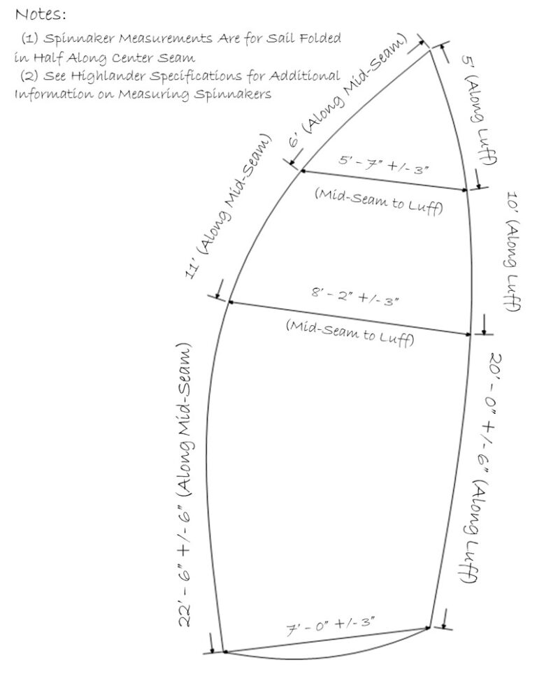
Figure 6. Spinnaker Measurements
